Tapered Carbon Fiber Tubes in Antenna & Mast Structures: Load Optimization from Geometry to Material Gradients
Author: Aohong Carbon Fiber Technology Center
1. Why Antenna and Mast Structures Need a “Tapered” Design
Load Gradient:
Wind and ice loads increase linearly or quadratically with height, resulting in maximum bending moments at the base and minimal stress at the top.
Electromagnetic Requirements:
A tapered carbon fiber profile helps optimize radiation patterns, reducing sidelobe interference. It also lowers wind drag coefficient by 10–20%.
Transport Constraints:
Segmented tapered tubes allow “nesting” (matryoshka-style) transport. Quick on-site assembly via spigot insertion or snap-fit connections significantly improves installation efficiency.
2. Tapered Carbon Fiber Tubes vs. Traditional Constant-Section Masts
| Metric | Constant-Section Aluminum Mast | Tapered Carbon Fiber Tube (Hybrid Structure) |
|---|---|---|
| Weight (15 m mast) | 85 kg | 28 kg (↓67%) |
| Base Bending Capacity | 1.0× | 1.4× (inertia scales with D⁴) |
| Top Displacement (1 kN wind) | 21 mm | 11 mm (↓48%) |
| EM Wave Transmission | 15% reflection | >90% transmittance (outer fiberglass layer) |
3. Four Key Design Dimensions for Load Optimization
Geometric Taper
- Taper ratio T = (D₁ – D₂) / L.
Recommended: 1:80–1:120 for antenna masts; 1:50–1:70 for portable base stations. - Half-cone angle θ/2 ≤ 3°: Ensures structural efficiency while avoiding high stress at the larger end.
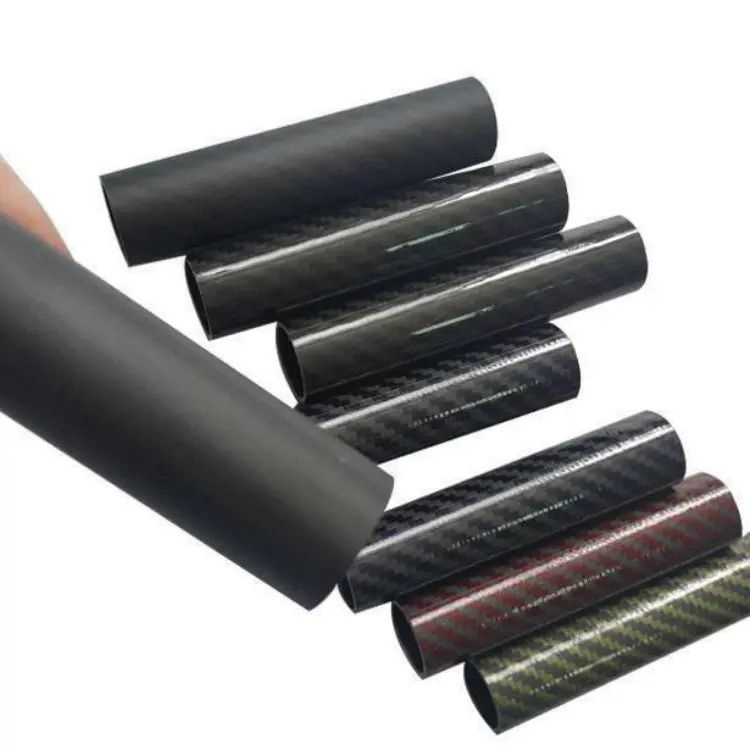
Material Gradient
- Inner Layer: T800 unidirectional carbon fiber for high modulus (160 GPa) bending resistance.
- Middle Layer: ±45° woven fabric enhances torsional rigidity and buckling resistance.
- Outer Layer: E-glass fabric for RF transparency, weather resistance, and cost control—delivering full electromagnetic transparency.
 Wall Thickness Gradient
 Wall Thickness Gradient
- Linear Gradient: Thickness transitions from 1.2 mm at the top to 4 mm at the base, achieving strength-matching design.
- Stepped Gradient: Every 500 mm a stepped increase, optimized for roll-wrapping or filament winding manufacturing.
Connection & Damping
- Tapered Spigot + Epoxy + Bolt-on Backplate: Enables 30-second assembly, supports up to 30 kN·m bending moment.
- Viscoelastic Damping Layer: Placed at D/4 position to suppress wind-induced vibrations (2–6 Hz), reducing vibration amplitude by 25%.
4. Typical Application Cases
| Application Scenario | Tube Specs | Optimization Features | Results |
|---|---|---|---|
| 5G Micro Base Station Mast | Φ60→Φ20 mm, L=6 m | Hybrid layup + embedded FBG fiber | 55% lighter, <5 mm top displacement |
| Satellite Antenna Support Arm | Φ40→Φ15 mm, L=2.7 m | Anisogrid ribs + out-of-autoclave curing | Specific mass <14 kg/m, 20% lighter than shell |
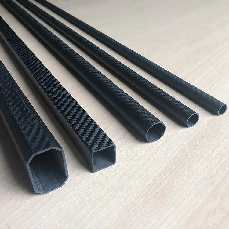
| Emergency Comms Mast (Vehicle) | Rectangular 80×40→40×20 mm, L=3 m | 3-level telescoping, quick-release locks | Setup in 30 s, withstands 200 N wind load |
5. Quick Selection Formulas
- Base Bending Moment: M = q·h² / 2, where q is wind load per unit length
- Required Inertia: I_req = M·h / (2·σ_allow)
- Use our online calculator: Input D₁, D₂, L → Get optimal wall thickness gradient and weight within 10 seconds.
6. Conclusion
Tapered Carbon Fiber Tubes deliver the ultimate solution for modern antenna and mast structures. Through a combination of geometric tapering, material gradients, and connection optimization, they simultaneously reduce weight, enhance stiffness, improve RF transparency, and simplify transport and installation. These advanced composite tubes are redefining structural design for high-performance communication systems.