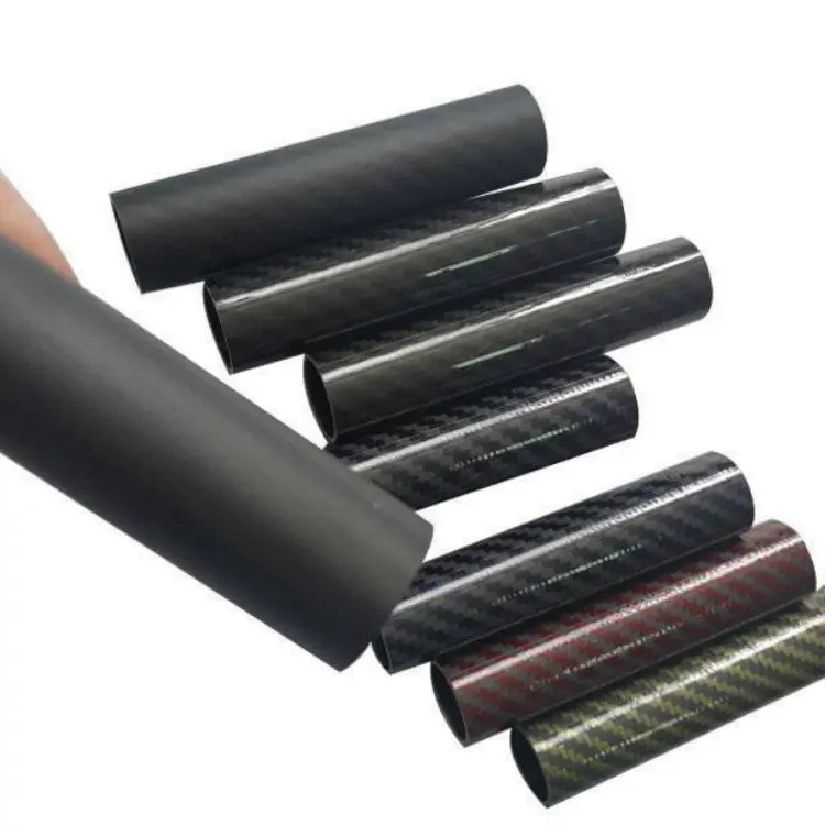
Carbon Fiber Telescoping Tubes: The “Lightweight Long Arm” for Robotics & Automation
— A Full‑Spectrum White Paper on Structural and Control Advantages —
Author: Aohong Carbon Fiber Application Center
1. Why Telescoping Tubes Need “Carbon Fiber”
Traditional aluminum or steel telescoping mechanisms face three core conflicts:
- Rigid Drop‑Off After Extension: Leads to end‑point vibration and loss of precision
- Weight Grows with Stroke: Causes motor overload and soaring energy consumption
- Metal Fatigue & Corrosion: Short maintenance intervals and high total cost of ownership
Carbon Fiber Telescoping Tubes solve all three pain points at once: lighter, stiffer, and far more durable.
2. Breakdown of Core Advantages
| Dimension | Traditional Aluminum Telescoping Tube | Carbon Fiber Telescoping Tube | Improvement |
|---|---|---|---|
| Linear Mass (Ø40×2 mm) | 550 g/m | 220 g/m | – 60 % |
| Effective Bending Stiffness (1 m Fully Extended) | 1.0× | 2.8× | + 180 % |
| Critical Speed (500 mm Cantilever) | 1 200 rpm | 2 100 rpm | + 75 % |
| Lifetime (500 k Cycles) | Visible rail wear | No visible damage | > 2× |
| Salt Spray (500 h) | Oxidation spots | Grade 0 corrosion | — |
3. Four Robotics & Automation Use Cases
SCARA 7th Axis
- Stroke: 400–800 mm, Load: 3 kg
- After replacing the aluminum arm with a carbon fiber telescoping tube, end‑point repeatability improved from ± 0.08 mm to ± 0.03 mm, and cycle time increased by 15 %.
Collaborative Robot Lift Column
- Dual‑stage oval telescoping tubes: 60×40 mm → 80×50 mm, t = 1.5 mm
- At 500 mm/s Z‑axis speed, peak motor current dropped by 22 %.
Automated Warehouse Retractable Fork
- Three‑stage square tubes: 50×50 mm, stroke 2.2 m
- Entire machine weight reduced by 34 kg, allowing the same servomotor to handle 50 % more cargo.
Solar Panel Cleaning Drone Telescoping Boom
- Four‑stage round tubes: Ø25×1.5 mm, fully extended 3 m at just 1.1 kg
- Saved 900 g of takeoff weight—flight time extended by 8 minutes.
4. Key Technical Details
Rails & Latches
- Embedded anodized aluminum rails with dry‑film lubricant (μ = 0.08), lifetime ≥1 million cycles
- Molded one‑piece lock, repeatability ± 0.02 mm, maintenance‑free
Wall‑Thickness Gradient Design
- Inner tubes taper wall thickness by 0.3 mm; outer tube root locally thickened by 2 mm—achieving “equal strength, unequal weight”
- 1:20 transition chamfer to avoid stress concentrations
Fiber Layup Strategy
- Outer layer: 0° UD for primary bending load
- Inner layer: ±45° to suppress torsion
- 90° hoop layer: prevents buckling
- Material: T700‑12K prepreg, autoclave cured, porosity < 1 %
Integrated Smart Sensing
- FBG fiber Bragg grating embedded in the tube wall for real‑time strain monitoring (± 10 µε)
- Direct CAN‑FD bus integration with robot controller—truly “structure as sensor.”
5. Three‑Step Selection Method
- Input Loads: maximum stroke L, end load W, max acceleration a
- Online Tool Output: number of stages, diameters, wall thicknesses, latch type
- Choose Finish:
- Standard Grade: T300 3K twill glossy, P1 tolerance
- Aerospace Grade: T800 UD matte, P0 tolerance, embedded FBG
6. Delivery Configurations
| Stages | Retracted Length | Extended Length | Outer Diameter Range | Latch Type |
|---|---|---|---|---|
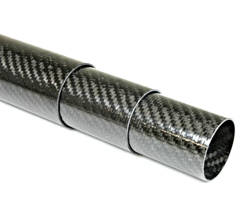
| 2‑stage | 300 mm | 600 mm | Ø25–40 mm | Quick‑release knob |
| 3‑stage | 400 mm | 1 200 mm | Ø30–60 mm | Spring‑ball lock |
| 4‑stage | 500 mm | 2 000 mm | Ø35–80 mm | Pneumatic lock |
7. One‑Sentence Summary
Carbon Fiber Telescoping Tubes let robots “reach farther, retract lighter, and move faster.”