Carbon Fiber Oval Tube Applications Analysis
A One-Stop Solution for Catheters, Aerodynamic Fairings, and Structural Components
Author: Aohong Carbon Fiber Application Center
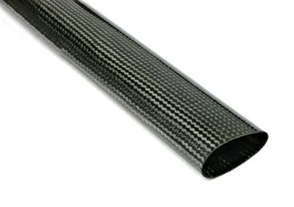
1. Why the Oval Cross‑Section Stands Out
Under equal perimeter, a Carbon Fiber Oval Tube offers both a higher moment of inertia and lower wind resistance than a round tube. Meanwhile, the difference between its major and minor axes provides directionally tunable stiffness, making it the ideal shape for catheters, aerodynamic fairings, and structural elements.
2. Three Major Application Scenarios
2.1 Catheters & Endoscopic Shafts
- Minimally Invasive: The oval profile reduces outer diameter at the same lumen size, minimizing patient trauma.
- High Pushability: UD fibers aligned along the major axis boost distal‑end rigidity by 25 %, delivering more direct push force.
- Multi‑Layer Co‑Extrusion: Combine an outer sheath with an inner oval tube to separate balloon expansion from guidewire channels.
- Roundness Retention: A high‑hardness A‑layer and low‑hardness B‑layer co‑extrusion maintain ≥ 85 % true roundness even after 20 pressurization cycles.
2.2 Aerodynamic Fairings & Ducts
- Lower Drag Coefficient (Cf): 15 %–30 % reduction in wind resistance versus round tubes—perfect for drone arms and EV battery‑pack cooling ducts.
- Lightweight “Oval‑Honeycomb” Core: Embed corrugated aluminum foil inside the oval tube to create a carbon‑fiber/foam sandwich, cutting weight by 40 %.
- Finish Options: 3K twill glossy or UD matte—to balance aesthetics and radar‑scattering requirements.
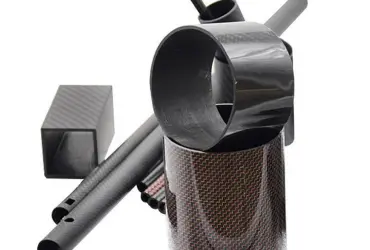
2.3 Structural Frames & Beams
- Robotic 7th Axis: A 40×25 mm oval tube delivers Iₓₓ = 4.8 cm⁴, a 60 % increase over a same‑perimeter round tube.
- Camera Sliders: Orient the minor axis downward to lower the center of gravity and use the major axis to support the camera platform—deflection < 0.1 mm/1 m.
- Foldable Trusses: Hinged oval tubes that self‑lock when deployed—35 % lighter than traditional square‑tube designs.
3. Manufacturing Methods & Selection Guide
| Process | Wall Thickness Range | Size Limit (Major Axis) | Surface Finish | Cost Factor | Best for |
|---|---|---|---|---|---|
| Roll-Wrapping | 0.8–3.0 mm | ≤ 120 mm | 3K Twill Glossy | 1.0× | Small batches, high‑precision catheters |
| Filament Winding | 1.0–6.0 mm | ≤ 300 mm | UD Matte | 1.2× | High‑volume aerodynamic fairings |
| 3D Braided RTM | 2.0–10.0 mm | ≤ 200 mm | Localized thickening | 1.5× | Impact‑resistant structural parts |
4. Quick 3‑Step Selection Method
- Input Loads: Bending moment (M), wind load (F), lumen diameter (D)
- Cross‑Section Calculation: Online tool provides optimal axis ratio (a/b) and wall thickness (t)
- Process Confirmation:
- Catheters → Roll‑wrapping
- Fairings → Filament winding
- Structural elements → 3D braided RTM
5. One‑Sentence Summary
The Carbon Fiber Oval Tube unites low drag, high stiffness, and designable anisotropy in a single profile—making your catheters finer and more precise, your fairings sleeker and lighter, and your structures stronger and more efficient.