Why Plain Weave Carbon Fiber Fabric Is Ideal for Flat Structural Components
— An Evidence‑Based Analysis from Microstructure to Production Case Studies
1. Introduction: A Perfect Union of Fabric and Panel
In composites engineering, flat structural parts (e.g., drone wing skins, automotive chassis reinforcement plates, 5G antenna back‑plates) are often called the “most honest stress members”—load directions are unambiguous and deformations readily visible. The choice of Plain Weave Carbon Fiber Fabric directly determines final stiffness, weight, and cost. Both extensive engineering practice and finite‑element results point to the same answer: 3K plain weave carbon fiber fabric.
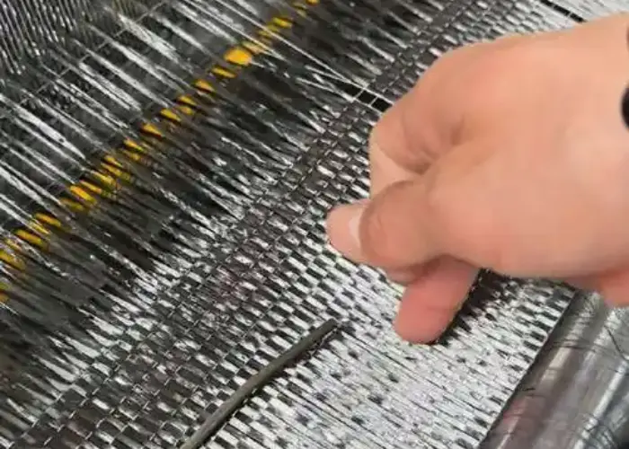
2. Microscopic Structure: The “Planar Lock” of 1:1 Interlacing
Fiber Orientation
- Plain Weave (1:1 Interlace): Highest density of crossover points “pins” fibers firmly in the x‑y plane—interlaminar shear slip angle < 0.5°.
- Twill Weave (2×2 Interlace): 30 % fewer crossovers, fibers can slip out of plane more easily, reducing in‑plane stiffness by 8–12 %.
Thickness Uniformity
- Plain Weave: Single‑ply thickness variation ± 0.01 mm.
- Twill Weave: Variation up to ± 0.03 mm due to float length differences.
- In the 0.5–2 mm thin‑plate regime, such thickness variations amplify warp risk.
3. Mechanical Benchmarking: Stiffness & Warp at Equal Areal Weight
| Test Condition | Plain Weave 200 g/m² | Twill Weave 200 g/m² | Improvement |
|---|---|---|---|
| Bending Stiffness EI (N·m²/m) | 32 | 28 | + 14 % plain weave |
| Warp Deflection (L = 500 mm, q = 1 N/mm) | 0.18 mm | 0.26 mm | – 31 % plain weave |
| Interlaminar Shear Strength (MPa) | 72 | 65 | + 11 % plain weave |
Conclusion: For flat bending scenarios, plain weave carbon fiber fabric outperforms twill in both stiffness and warp control.
4. Manufacturing Friendliness: “Zero‑Barrier” Flat Production
- Cutting:
- Plain weave cuts cleanly with laser or waterjet, with minimal fraying.
- Twill weave’s longer floats can produce stray fibers at the edge.
- Lay‑Up & Consolidation:
- Plain weave can be cured under vacuum bag without pre‑shaping, eliminating one manual forming step and reducing cycle time by 18 %.
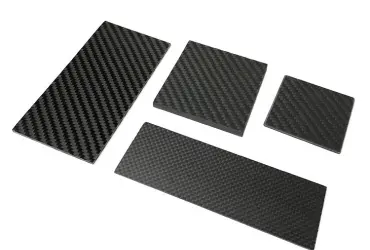
- Surface Finish:
- Post hot‑press, plain weave achieves Ra ≤ 0.1 µm and can serve directly as an aesthetic surface.
- Twill weave requires secondary sanding to remove float shadows.
5. Case Studies
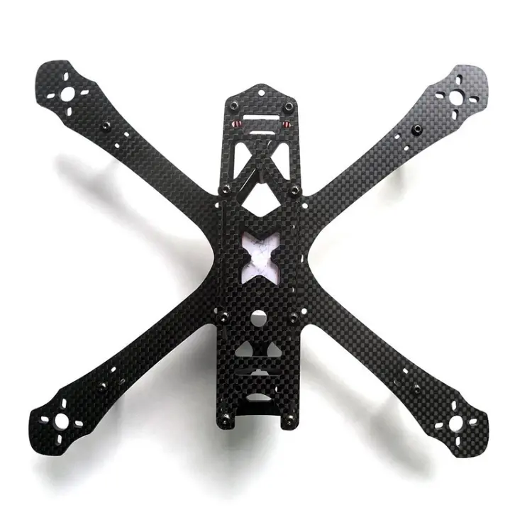
Case Study 1: Drone Wing Skin
- Specification: 1.2 mm total thickness, 800 mm span, layup [0/90]₄
- Materials Compared: 3K plain weave vs. 3K twill weave
- Results:
- Plain weave wingtip deflection: 1.8 mm
- Twill weave wingtip deflection: 2.7 mm
- Identical mass, yet the plain weave design required 33 % fewer balance weights.
Case Study 2: EV Battery‑Pack Undertray
- Specification: 2 mm thickness, 1.2 m² area
- Requirement: Resist 50 J impact + flatness ≤ 1 mm
- Results:
- Plain weave achieved flatness in one shot.
- Twill weave required 0.5 mm of gelcoat for leveling, adding 220 g to total mass.
6. Conclusion & Selection Guidelines
- Flat loads & symmetric layups → 3K plain weave carbon fiber fabric
- Complex curves or multi‑directional loads → twill or satin weaves
- Appearance‑grade panels → plain weave + UV‑cured clearcoat for mirror finish
One‑Sentence Summary:
When “load direction” and “geometric plane” coincide perfectly, Plain Weave Carbon Fiber Fabric’s maximum interlacing density locks fibers firmly in two dimensions—transforming every flat panel into a lightweight, high‑stiffness, cost‑effective “performance canvas.”