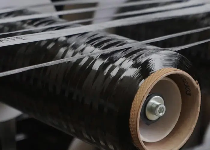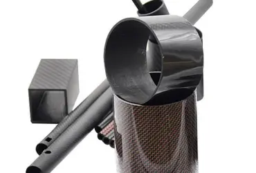
1. Overview
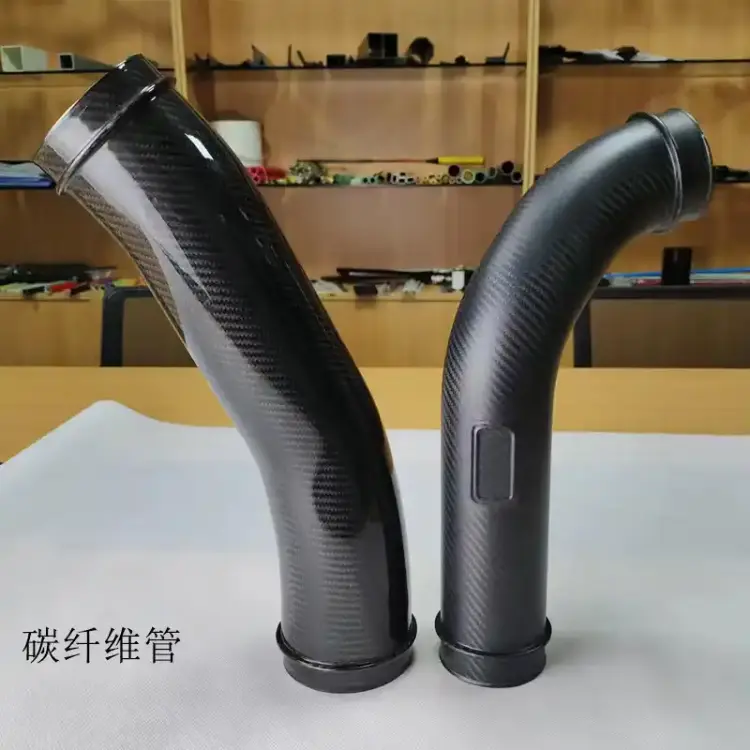
The carbon fiber intake tube is a core component of the engine intake system, manufactured from carbon-fiber composite. Its lightweight construction and low thermal conductivity enhance intake efficiency. A finely finished inner surface reduces airflow turbulence, and improved thermal insulation compared with cast aluminum lowers intake temperature rise from engine heat — a decisive advantage for sustained high-load operation. Compared with conventional metal piping, weight is reduced by over 50%, while impact resistance and wear resistance ensure long-term, stable performance.
2. Technical Specifications
| Key Parameter | Value | Test Conditions / Notes |
|---|---|---|
| Weight | 1.5 kg | Single standard length tube (400 mm) |
| Thermal conductivity | 200 W/m·K | Longitudinal test at ambient temperature |
| Inner surface roughness | Ra < 0.1 μm | Measured with laser profilometer |
| Inner diameter | 90 mm | Cross-section measured at mid-span |
| Airflow capacity | 700 m³/h | Simulated flow at standard atmospheric pressure |
| Continuous operating temperature | 300–400 °C | Continuous run in oxidizing environment |
| Resonant frequency | 250 Hz | Measured on a modal vibration test system |
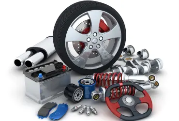
3. Typical Applications
- High-performance racing: Compatible with models such as Honda FK8 and Toyota GR Yaris. Improves turbo response and peak power—especially noticeable on Stage 2 tuned cars.
- Street performance vehicles: Offers power upgrades for enthusiasts; improves throttle response and mid-range acceleration while enhancing engine-bay aesthetics.
- Motorcycles: Used on track and street bikes to reduce unsprung/rotating mass and improve handling stability.
- Specialized equipment: Serves as intake components in high-temperature systems where temperature resistance ensures continuous operation.
4. Installation & Usage Guidelines
- Preparation: Required tools include a ratchet set and hex keys. Protect vehicle paintwork with masking tape and follow the vehicle-specific service manual closely.
- Removal of OEM parts: Disconnect the negative battery terminal first. Carefully remove the MAF sensor, clamps and vacuum lines to avoid sensor damage.
- Assembly: Align the air filter and tube interfaces, hand-tighten clamps first and then final-tighten to recommended torque. Avoid over-tightening which may crack carbon fiber.
- Commissioning & maintenance: After installation, idle the engine for 5 minutes to stabilize airflow. Clean reusable filters periodically. Inspect tube sealing every 20,000 km.
5. Frequently Asked Questions
- Q: How does it compare with OEM aluminum piping?
- A: Inner surface roughness is reduced by over 90%, estimated turbulence reduction ~30% (estimated). Improved thermal insulation lowers intake temperature by approximately 5–8 °C and can increase power output by 3–5% (estimated).
- Q: Is there an aging risk under high temperature?
- A: The tube is capable of stable long-term operation in oxidizing environments at 300–400 °C. Near turbocharger regions, service life is estimated at over 80,000 km (estimated); for extreme heat exposure use thermal shielding.
- Q: Is ECU remapping required after installation?
- A: Large bore tubes (>80 mm) are recommended to be paired with an ECU program update. Small bore, OEM-compatible variants generally fit stock systems without additional tuning.
- Q: How to check tube sealing?
- A: Apply soapy water to joints when the engine is running—no bubbles indicates a good seal. Manifold pressure fluctuation at idle should be ≤ 0.5 kPa (estimated).
- Q: What about maintenance cost compared to metal piping?
- A: Initial purchase cost is 3–4× higher, but reusable filters and lower annual maintenance reduce yearly costs by ~60%, bringing overall lifecycle cost roughly to parity (estimated).
6. Conclusion & Engineering Recommendations
The carbon fiber intake tube achieves an optimal balance of lightweight construction, high flow and thermal resistance. It is an excellent choice for turbocharged engines and systems subject to sustained high load.
Selection advice
Match inner diameter to engine displacement: for 2.0T engines, prefer 90–100 mm. Naturally aspirated engines may use 70–80 mm (estimated). Avoid oversizing which can reduce low-end torque.
Installation standard
Have installation performed by qualified technicians. Recommended torque setting: 15–20 N·m (estimated). Ensure mating surfaces are flat and free of stress concentrations.
Warranty guidance
Select manufacturers offering ≥ 2-year warranty covering material cracking and air-tightness failure. Avoid non-standard products without test documentation.