Thickness Reinforcement & Transition Design White Paper
— Achieving Strength Without Sacrificing Weight
Author: XXX Carbon Fiber Technology Team
Publish Date: July 25, 2025
1. Introduction
The lightweight myth of carbon fiber is often oversimplified as “the thinner, the lighter.” In reality, structural safety hinges on a targeted local thickness reinforcement combined with a progressive transition design—concentrating load-bearing capacity while avoiding stress concentrations. Drawing on case studies from aerospace, automotive, wind energy, and sporting goods, this paper systematically explains how to add material intelligently, achieving gram-level weight gains for ton‑scale performance improvements.
2. Design Principles
2.1 Load-First Approach
- Use finite‑element analysis to identify the primary load paths.
- Classify three critical zones:
- Zone A: High tension/compression or shear concentration (e.g., bolt holes, bonded joints)
- Zone B: High bending moments (e.g., cantilever roots, wing rib flanges)
- Zone C: Impact or fatigue cycles (e.g., suspension arm ball‑joint seats)
2.2 Progressive Transition
- Thickness gradient: ≤ 1:20 for aerospace, ≤ 1:10 for automotive
- Transition length (L): ≥ 3 × tmax to avoid 90° steps
- Combine tapered ply-drop with staggered drop-off for dual safety
2.3 Material Matching
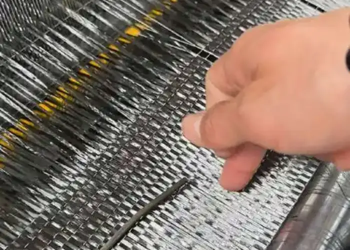
- Reinforcement layers: High‑modulus UD tape or 3K plain‑weave prepreg
- Transition layers: ±45° woven fabric or chopped‑fiber mat to suppress delamination
- Around bonded or riveted holes: Local 3D‑woven sleeve or metal insert for “soft transition”

3. Typical Reinforcement–Transition Structures
| Industry | Critical Location | Reinforcement Type | Transition Strategy | Measured Benefit |
|---|---|---|---|---|
| Aerospace | Wing skin–rib junction | +2 mm UD at rib flange | 1:25 taper + 10 mm stagger | –9 % weight, +35 % fatigue life |
| Automotive | Battery-box lifting lugs | +6 layers 3K plain weave | Double‑sided 1:12 step transition | +60 g weight for 15 kN pull‑off pass |
| Wind | Blade spar cap | 60 mm stack 12K UD at root | 1:30 linear taper | –18 % spar mass, –22 % root bending moment |
| Sporting | Road‑bike BB shell | Metal BB insert + 2 mm wrap | 3D‑woven sleeve transition | +12 % stiffness, zero creaking complaints |
4. Key Manufacturing Considerations
4.1 Layup
- Laser projection alignment: ± 0.5 mm precision to control ply offset
- Automated fiber placement (AFP): Variable tape‑width function in transition zones to reduce manual trimming
4.2 Curing
- Zoned compaction: Independent bladder for reinforced areas to prevent under‑pressure voids
- Post‑cure RTM: Infuse micro‑cracks in tapered zones, boosting interlaminar shear strength (ILSS)
4.3 Inspection
- Industrial CT & ultrasonic C‑scan: Ensure void content < 1 % in transition regions
- Digital image correlation (DIC): Verify strain‑concentration factor Kt ≤ 1.3
5. Common Pitfalls
- Reinforcing in CAD only, without validating the transition—leading to delamination rejects
- Blind use of 12K tow for reinforcement—causing premature local buckling
- Entire transition region in UD—insufficient transverse stiffness and brittle splitting
6. Design Workflow Overview
- Identify loads & failure modes
- Topology & laminate optimization
- Automated transition‑curve generation (CATIA/Fibersim)
- Process–inspection closed‑loop validation
7. Conclusion
Reinforcement is not about “adding material” but “applying the right addition”: the right material, in the right place, with the right method. XXX Carbon Fiber delivers a complete product chain—from UD prepregs to 3D‑woven sleeves—paired with AI‑driven transition‑optimization software, enabling megapascal‑level strength gains with only gram‑level weight increases.
Contact our structural engineers today to receive a customized reinforcement–transition simulation report.

