Carbon Fiber Tube Wall Thickness & Tolerance Design Guide
— Achieving the “Golden Ratio” Between Performance & Cost
Publish Date: July 25, 2025
Author: Hengshui Aohong
1. Scope & Definitions
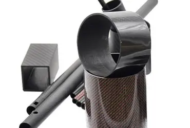
This guide applies to continuous-fiber-wound, round-section carbon fiber tubes (outer diameter Φ 1–60 mm, length ≤ 5 m). It covers wall thickness selection, tolerance classes, and inspection methods for B2B industrial applications.
2. Recommended Wall Thickness
2.1 Quick Selection by Outer Diameter
| Outer Diameter Φ (mm) | Minimum Thickness tₘᵢₙ (mm) | Typical Thickness tₜʸₚ (mm) | Maximum Thickness tₘₐₓ (mm) | Typical Applications |
|---|---|---|---|---|
| 1–6 | 0.3 | 0.5–1.0 | 1.5 | RC airframe frames, medical device needles |
| 6–15 | 0.5 | 1.0–2.0 | 3.0 | Photography light stands, telescoping masts |
| 15–30 | 1.0 | 2.0–3.5 | 4.5 | Robot linkages, automotive drive shafts |
| 30–60 | 1.5 | 3.0–5.0 | 6.0 | Industrial rollers, wind turbine pitch control rods |
2.2 Variable-Thickness Design
For local reinforcement (e.g., threaded inserts, bearing seats), use 3–20 stepped thicknesses between 1.5–6 mm. This avoids stress concentrations while reducing overall weight by 8–15 %.
3. Tolerance Classes & Selection
3.1 Class Definitions
| Class | Outer Diameter Tolerance | Inner Diameter Tolerance | Wall Thickness Tolerance | Typical Applications |
|---|---|---|---|---|
| P0 | ± 0.02 mm | ± 0.02 mm | ± 0.03 mm | Medical catheters, optical barrels |
| P1 | ± 0.05 mm | ± 0.05 mm | ± 0.05 mm | Aerospace components, robotic joints |
| P2 | ± 0.10 mm | ± 0.10 mm | ± 0.10 mm | General industrial structures, sports equipment |
3.2 Process Capability
- Filament winding + CNC OD grinding: stable achievement of P1 tolerance.
- Mandrel-less grinding + inline laser gauging: P0 requires 3K thin-wall prepreg and secondary curing.
4. Key Design Considerations
4.1 Wall Thickness & Ply Coupling
- Single prepreg layer: 0.15 mm (1K) to 0.30 mm (3K/12K)
- Continuous plies of the same orientation: ≤ 4 layers or ≤ 1 mm total thickness to prevent delamination
- Transition zones: 1:20 taper ratio, ply offsets ≥ 5 mm
4.2 Cure-Shrinkage Compensation
Use the empirical formula:
Δt ≈ 0.02 × t_nominal
Design nominal thickness + 2 % to offset resin cure shrinkage.
4.3 Machining Allowance
For threaded or metal-sleeve ends, leave an extra 0.3–0.5 mm allowance to ensure post-machining thickness ≥ tₘᵢₙ.
5. Inspection & Acceptance
- Go/no-go gauges + pneumatic micrometer: 100 % inline OD/ID inspection
- Ultrasonic C-scan: verify wall-thickness uniformity; void content ≤ 1 %
- Reporting: each batch includes a “wall thickness contour map” and a “tolerance Cpk ≥ 1.33” certificate.
6. Quick Calculation Formula
t_min ≥ (P · Φ) / (2 · σ_allow) + Δ_mach
- P: internal or equivalent external pressure
- σ_allow: use 600 MPa (T300 epoxy)
- Δ_mach: machining allowance, typically 0.2 mm
7. Common Pitfalls
- Ultra-thin walls (≤ 0.5 mm) with 12K tow → prone to buckling; yield < 70 %.
- Over-specifying P0 tolerance → +30 % cost for non-critical parts.
- Ignoring thermal expansion → metal inserts require ≥ 0.05 mm clearance.
8. Contact & Custom Solutions
Need precision tolerances or variable-thickness designs? Submit your outer diameter, load conditions, and operating environment. We’ll deliver a manufacturability assessment (DFM) report within 24 hours.