Carbon Fiber Orientation’s Decisive Impact on Stiffness & Strength
— From 0° to 90°, Ensuring Every Fiber Works in the Optimal Direction
Author: Aohong Carbon Fiber Structural Technology Team
Publish Date: July 25, 2025
1. One‑Sentence Takeaway
Fiber orientation = load direction. When aligned, tensile strength can increase 5–10×; misaligned, even the thickest laminate will fail prematurely.
2. Orientation Definitions at a Glance
- 0° (Longitudinal): Along tube/plate axis; primary tension and compression
- 90° (Transverse): Perpendicular to axis; resists lateral loads and Poisson’s effect
- ±45° (Shear): Crossed at ±45°; carries shear and torsion loads
- Quasi‑isotropic stack: Combination of 0°/±45°/90° for balanced multi‑axial performance
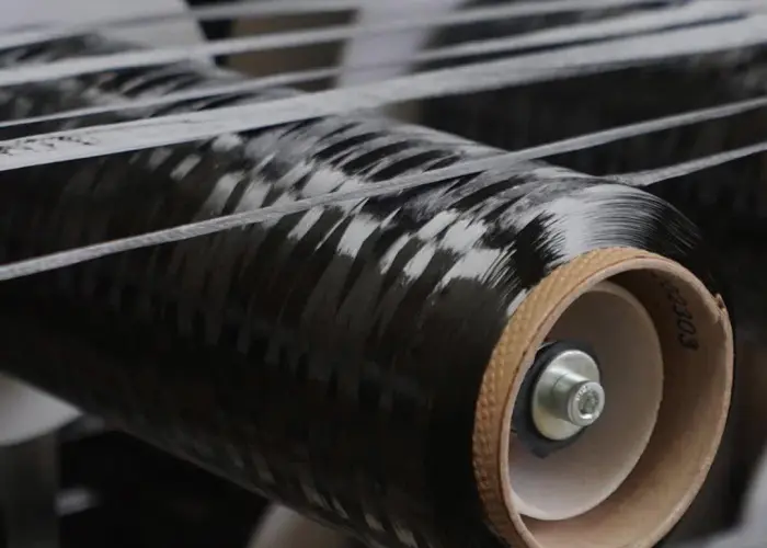
3. UD Tape Orientation vs. Performance
(T300 epoxy, Vf = 60%)
| Orientation | Tensile Modulus (GPa) | Tensile Strength (MPa) | Interlaminar Shear (MPa) | Typical Applications |
|---|---|---|---|---|
| 0° | 135 | 2,000 | 80 | Wing spar caps, bicycle chainstays |
| 90° | 10 | 50 | 80 | Rarely alone; prevents Poisson‑induced cracking |
| ±45° | 15 | 250 | 120 | Drive shafts, cantilever webs (torsion) |
Key Insight: 0° stiffness is 13.5× that of 90°; ±45° shear strength is 50% higher.
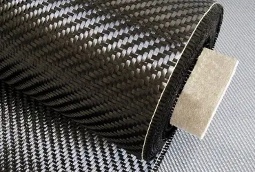
4. Woven Fabric Orientation & Performance Variations
- Plain Weave: 50% 0°/50% 90°—good transverse stiffness, ideal for shell skins
- Twill Weave: Adjustable 0°/90° ratio + optional ±45° reinforcement—excellent drape on complex curves
- 3D Weave: Through‑thickness fibers boost interlaminar shear by 30%—for high‑impact applications
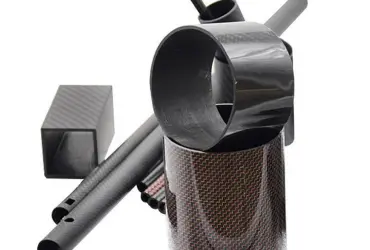
5. Real‑World Layup Case Studies
Case 1: UAV Wing Spar
- Objective: High bending stiffness + lightweight
- Stack:
[(0°/0°/±45°/90°)_S]_2 - Result: 50% 0° → 4.2× bending stiffness; ±45° prevents shear buckling; 90° stops edge splitting
Case 2: Automotive Drive Shaft
- Objective: High torsional strength
- Stack:
[(±45°)_4/0°_2] - Result: 66% ±45° → 3.8× torque capacity; 0° layers maintain axial stiffness, avoiding high‑speed resonance
Case 3: Bicycle Seatpost
- Objective: Comfort + pedaling rigidity
- Stack:
[(0°/90°/±30°)_S] - Result: ±30° layers deliver controlled flex to absorb vibration; 0° maintains pedaling stiffness; 90° prevents clamp‑induced splitting
6. Three‑Step Design Method
- Load Decomposition: FEA to extract principal stresses σ₁, σ₂ and shear τ₁₂
- Orientation Matching:
- σ₁ → 0°
- σ₂ → 90°
- τ₁₂ → ±45°
- Proportion Optimization:
- Iterate ply percentages until Tsai‑Wu failure index < 1
- Verify interlaminar shear and buckling safety factors
7. Common Pitfalls
- Pitfall A: Blindly adding 0° plies → lateral cracking & delamination
- Pitfall B: Ignoring ±45° layers → early buckling under torsion
- Pitfall C: Too few 90° plies → Poisson effect causes edge separation
8. Conclusion
Carbon fiber’s full potential is only unleashed when fibers are correctly oriented. Direct each fiber toward its optimal load path—this is Aohong Carbon Fiber’s “direction‑level” solution for maximum stiffness, strength, and reliability.