Carbon Fiber Profiles Selection Guide — How to Choose Carbon Fiber Profiles ?
One‑Stop Quick‑Reference from “Section Shape” to “Performance”
Version: 2025‑07‑25 | For Online Profile Sizing
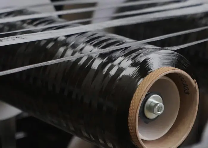
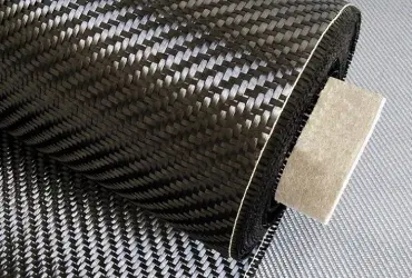
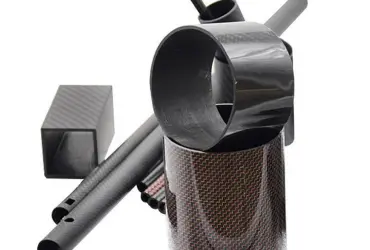
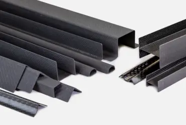
1. Profile Overview
Categories: ① Round Tubes ② Angle Profiles ③ Channel Profiles ④ Custom Extrusions ⑤ Beams
2. 3‑Step Selection Method (30 s)
- Load Scenario → 2. Cross‑Section Shape → 3. Fiber Grade & Surface Finish
Lock in your profile in 30 s; get a DFM report in 5 min.
3. Standard Section Lookup Table
| Profile Type | Nominal Size (mm) | Wall Thickness t (mm) | Moment of Inertia Ix (cm⁴) | Linear Mass (g/m) | Typical Use |
|---|---|---|---|---|---|
| Round Tube | Φ20 × 1.5 | 1.5 | 0.98 | 110 | UAV arms |
| Round Tube | Φ30 × 2.0 | 2.0 | 3.14 | 220 | Robot linkages |
| Square Tube | 20 × 20 × 1.5 | 1.5 | 1.33 | 145 | Camera mounts |
| Angle Profile | 25 × 25 × 2 | 2.0 | 1.56 | 190 | Structural frames |
| Channel Profile | 40 × 20 × 2 | 2.0 | 4.80 | 260 | Industrial rails |
| Custom Section | As required | 0.5–10 | — | — | Crash beams, custom |
4. Fiber Grade & Layup Recommendations
| Fiber Grade | Tow Size | Modulus (GPa) | Strength (MPa) | Suggested Layup | Keywords |
|---|---|---|---|---|---|
| T300 | 3K / 12K | 230 | 3,530 | [0°/±45°/90°]ₛ | General‑purpose, cost‑effective |
| T700 | 12K | 230 | 4,900 | [0°₂/±45°]ₛ | High‑strength, UAV |
| T800 | 12K | 294 | 5,490 | [0°₃/±45°/90°]ₛ | Aerospace, racing |
| M40J | 3K | 377 | 4,410 | [0°₄/90°]ₛ | Ultra‑modulus, optics |
5. Surface Finish Options
| Finish | Gloss Level | Features | Additional Cost |
|---|---|---|---|
| 3K Twill Glossy | 90 GU | Mirror‑like, showcase weave | + 8 % |
| 3K Twill Matte | 15 GU | Anti‑fingerprint, low glare | Base price |
| UD Matte Black | 5 GU | No visible weave, ultra‑light | – 5 % |
| Color Silk‑Screen | — | Custom logos & scales | + 10 % |
| Anodized Inserts | — | Metal interface integration | Per insert |
6. Tolerance & Length Range
| Class | Profile Tolerance | Wall Tolerance | Straightness | Max Length | Inspection Method |
|---|---|---|---|---|---|
| P0 | ± 0.05 mm | ± 0.05 mm | 0.2 mm/m | 2,000 mm | CMM |
| P1 | ± 0.10 mm | ± 0.10 mm | 0.5 mm/m | 4,000 mm | Laser scan |
| P2 | ± 0.20 mm | ± 0.15 mm | 1.0 mm/m | 6,000 mm | Calipers |
7. Joining & Post‑Processing
- Molded‑in aluminum/titanium sleeves: ± 0.02 mm tolerance, press‑fit, no adhesive
- CNC drilling, tapping & face milling: hole position ± 0.05 mm
- Laser marking: QR‑code traceability, batch numbers
8. 60‑s Selection Example
Scenario: Six‑axis robot link requiring high torsional stiffness
- Shape: Φ25 × 1.5 mm Round Tube
- Fiber: T700 12K
- Layup: [0°₃/±45°]
- Finish & Class: 3K Matte & P1 tolerance
→ Result: – 52 % weight vs. 6061‑T6, + 4.1× torsional stiffness, cost‑neutral.
9. Online Tool & Delivery
- 3D Profile Library: STEP download with one click
- Instant Section Recommendation & Quote: enter load, get result in 30 s
- Lead Times: Small runs in 5 days; large batches in 10 days
- Multi‑Process Support: 6 m continuous pultrusion, autoclave, compression molding
10. Common Pitfalls
- “Thicker is always better” → increases weight, lowers resonance frequency
- Ignoring insert integration → assembly cracks at interfaces
- Only choosing ultra‑high‑modulus fiber → brittleness and high cost
Select the right shape, fiber grade & finish, and each carbon fiber profile becomes a “gram‑Newton” performance multiplier.
Access our online profile selector now to lock in your custom solution in 30 seconds!