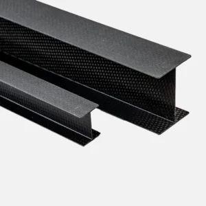
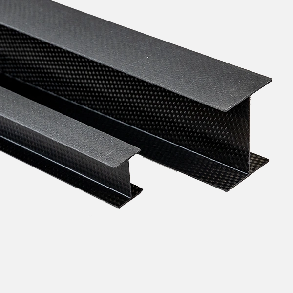
Carbon Fiber I‑Beam & H‑Beam Profiles
— Integrated I‑Shape & Double‑T Pultruded Sections · Ultra‑High Specific Stiffness · Modular Structural Backbone
1. Product Definition
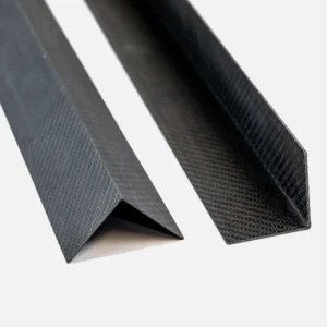
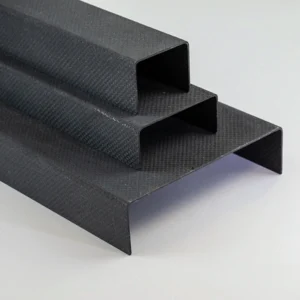
Carbon Fiber I‑Beams and H‑Beams are symmetrical, pultruded profiles made in a single step with T700/T800 carbon fibers in a 0°/±45°/90° hybrid layup. Continuous fibers run unbroken through flange and web, with no adhesive joints or metal inserts. Available as “I‑shape” or “double‑T” cross‑sections, they combine ultralight weight, exceptional flexural rigidity, and high shear resistance.
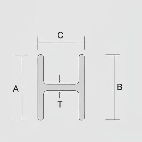
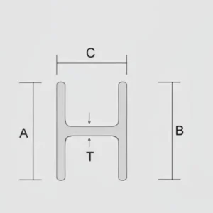
2. Section Naming Convention
| Code | Type | Description |
|---|---|---|
| I‑100×50×3 | I‑Beam | Height 100 mm, Flange Width 50 mm, Wall Thickness 3 mm |
| H‑120×80×4×6 | H‑Beam | Height 120 mm, Flange Width 80 mm, Web 4 mm, Flange 6 mm |
3. Common Stock Sizes (Straightness ≤ 0.5 mm/m)
| Series | H (mm) | B (mm) | t (mm) | Weight (kg/m) | Ix (cm⁴) | Typical Applications |
|---|---|---|---|---|---|---|
| I‑50×25×2 | 50 | 25 | 2.0 | 0.38 | 14.2 | UAV frames, small trusses |
| I‑60×30×2.5 | 60 | 30 | 2.5 | 0.57 | 24.6 | Camera booms, robotic crossbeams |
| I‑80×40×3 | 80 | 40 | 3.0 | 0.92 | 58.4 | Industrial jigs, measurement arms |
| I‑100×50×3 | 100 | 50 | 3.0 | 1.21 | 122 | Rowing keels, RC wing spars |
| I‑120×60×4 | 120 | 60 | 4.0 | 1.90 | 235 | Curtain wall beams |
| H‑120×80×4×6 | 120 | 80 | 4/6 | 2.45 | 320 | Wind‑turbine maintenance platforms |
| H‑150×100×5×8 | 150 | 100 | 5/8 | 4.10 | 780 | Roll cages, RV chassis |
| H‑200×120×6×10 | 200 | 120 | 6/10 | 7.20 | 2 150 | Large UAV main spars |
Customizable up to: Height 300 mm, Flange Width 200 mm, Wall Thickness 2–12 mm, Length ≤ 6 m.
4. Mechanical Properties (Example: I‑100×50×3, Epoxy Cure)
| Property | Value |
|---|---|
| Density | 1.58 g/cm³ |
| 0° Tensile Strength | 2 600 MPa |
| Flexural Modulus | 150 GPa |
| Shear Strength (Web) | 95 MPa |
| Operating Temperature | −50 °C to 180 °C |
| Coefficient of Thermal Expansion | 1.2 × 10⁻⁶ /°C |
5. Manufacturing Process
- Pultrusion + Hot‑Press Cure
- Impregnate continuous carbon fiber with epoxy resin
- Pultrude through I/H die at 150 °C
- Traction and cut at 1–2 m/min
- Automated Fiber Placement (AFP)
- Deposit 0°/±45° plies for large H‑beams
- Autoclave cure for complex curves
- Post‑Processing
- CNC face milling, flange drilling, M6–M16 tapping
- Optional aluminum/titanium inserts
6. Joining & Assembly
- Flange Bolting: M6–M12 stainless bolts, 25 N·m torque
- Angle Brackets: Carbon fiber corner plates (90°/120°), bonded + riveted
- Insertion Joints: 2 mm web slots accept carbon interlock plates, boosting shear capacity by 40%
7. Typical Applications
- Drones: I‑80×40×3 as 2 m wing spar—55 % lighter than aluminum, < 1 mm deflection @ 150 N
- Automotive: H‑150×100×5×8 as roll‑cage beam—2× collision energy absorption vs. steel
- Architecture: I‑120×60×4 as curtain‑wall beam spanning 4 m under 2 kN/m² load
- Wind Energy: H‑200×120×6×10 as tower platform beam—2000 h salt‑spray resistance
- Robotics: I‑60×30×2.5 as SCARA crossbeam—± 0.02 mm positioning repeatability
8. Ordering & Delivery
- MOQ: 1 unit in stock; 50 units custom
- Lead Time: Stock 3 days; custom 7–10 days; AFP large beams 15 days
- Packaging: Film wrap → EPE foam → Carton; wooden crate for > 2 m lengths
- Certifications: Batch material reports, RoHS, REACH, DNV‑GL (marine)
Offline Contracts
All sales of our carbon fiber materials are conducted through offline contract agreements to ensure each order precisely meets your specifications, compliance requirements, and agreed payment terms. Please contact our sales team to initiate the contract process and discuss project details.
| name | value | unitCode | unitText |
|---|---|---|---|
| MOQ | 50 | PCS | |
| Lead Time | 5–20 | business days | |
| Material | Carbon Fiber | ||
| Size | Customizable (cross section dimensions / length) |
Resources

Carbon Fiber I‑Beams & H‑Beams pack the structural backbone of steel into aluminum‑weight profiles—delivering steel‑like rigidity and carbon‑fiber elegance.