Carbon Fiber Tube Selection Guide — How to Choose Carbon Fiber Tubes ?
Quick‑Reference with One Diagram & Three Tables for Dimensions, Wall Thickness & Surface Finish
Version: 2025.07.25 | For Online Sizing Tool
1. Selection Workflow
Load Path → Dimension Definition → Wall Thickness Calculation → Surface Finish → Tolerance Class
(First‑pass screening in 30 s; lock in final specs within 5 min)
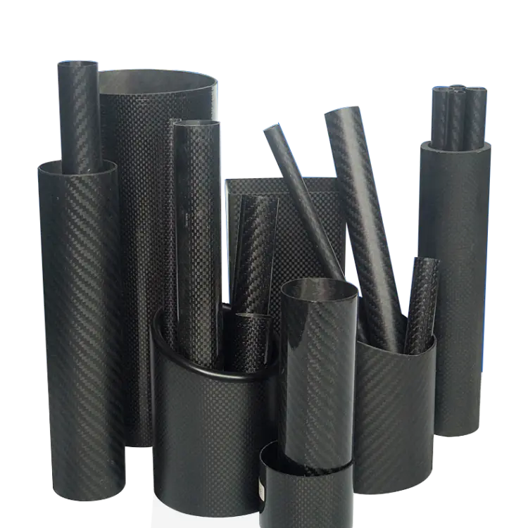
2. Dimension Lookup Table
(Outer Diameter Φ vs. Inner Diameter & Wall Thickness, Typical Use & Linear Mass)
| Outer Diameter Φ (mm) | Common Inner Diameter (mm) | Recommended Wall Thickness t (mm) | Typical Application | Linear Mass* (g/m) |
|---|---|---|---|---|
| 4–6 | 2–4 | 0.3–0.8 | FPV drone arms, medical guide tubes | 8–18 |
| 8–12 | 5–9 | 0.8–1.5 | Camera gimbals, robotic linkages | 25–55 |
| 15–20 | 12–17 | 1.0–2.0 | Sprayer booms, automotive cables | 55–110 |
| 25–30 | 21–26 | 1.5–3.0 | Industrial rollers, surveying spars | 120–220 |
| 35–60 | 29–54 | 2.0–5.0 | Wind‑turbine webs, heavy‑duty arms | 250–650 |
*Estimated for T300 epoxy at Vf = 60%.
3. Three‑Step Wall Thickness Decision Method
Step A: Input Loads
- Bending moment M (N·m)
- Torsion moment T (N·m)
- Axial force F (N)
Step B: Quick‑Calc Formulas

- Where:
- r = mean radius
- σ_allow = 600 MPa (T300) or 800 MPa (T800)
- τ_allow = interlaminar shear limit
Step C: Safety Factors
- Dynamic loads × 1.5
- Impact loads × 2.0
- UAV applications × 1.3 (priority on weight saving)
4. Surface Finish Comparison Table
| Surface Finish | Gloss Level | Features | Typical Use | Extra Cost |
|---|---|---|---|---|
| 3K Twill Glossy | 90 GU | Mirror‑like, 3D texture | Display parts, auto exteriors | +8 % |
| 3K Twill Matte | 15 GU | Low‑glare, fingerprint resistant | Drone arms, interior trim | Base price |
| UD Matte Black | 5 GU | No visible weave, ultra‑light | FPV racing frames, industrial | –5 % |
| Color Silk‑Screen | — | Logos & scales | Racing, surveying units | +12 % |
| UV Self‑Healing Clearcoat | — | Scratch self‑repairs in 30 s | Removable tooling fixtures | +15 % |
5. Tolerance & Quality Inspection Classes
| Class | OD Tolerance | Wall Thickness Tolerance | Straightness | Typical Use | Inspection Method |
|---|---|---|---|---|---|
| P0 (Precision) | ± 0.02 mm | ± 0.03 mm | ≤ 0.05 mm/m | Medical, optics | CMM + laser scan |
| P1 (Aerospace) | ± 0.05 mm | ± 0.05 mm | ≤ 0.10 mm/m | UAVs, robotics | Go/No‑Go + ultrasonic |
| P2 (Industrial) | ± 0.10 mm | ± 0.10 mm | ≤ 0.30 mm/m | General structures | Calipers + visual check |
6. Fast‑Track Online Sizing Tool
- Input outer diameter Φ, loads (M/T/F), and safety factor
- Output recommended wall thickness t, linear mass, price range
- Switch finishes (glossy/matte/UD) for real‑time visual preview
- Download STEP model & DFM report with one click
7. Common Pitfall Warnings
- Pitfall 1: “Thicker = safer” → adds weight & can trigger resonance
- Pitfall 2: Unnecessary P0 tolerance → doubles cost; usually overkill for UAVs
- Pitfall 3: Ignoring inner chamfer → stress concentrates, causing end fractures; always use R ≥ 0.5 mm
8. Contact & Delivery
- Prototypes in 48 h; small runs in 5 days; large batches in 15 days
- One‑stop services: CNC post‑processing, insert bonding, dynamic balancing
- Ensure every carbon fiber tube delivers maximum performance in the right dimensions, wall thickness, and surface finish.
Ready to optimize your carbon fiber tubes? Visit our online sizing tool or Contact Us for a personalized quote.

