—A practical checklist for engineers who treat “weight reduction” as a KPI
Intro
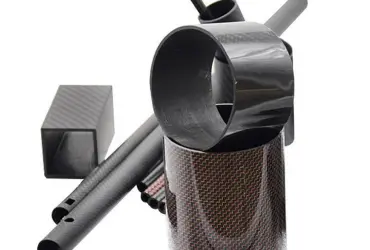
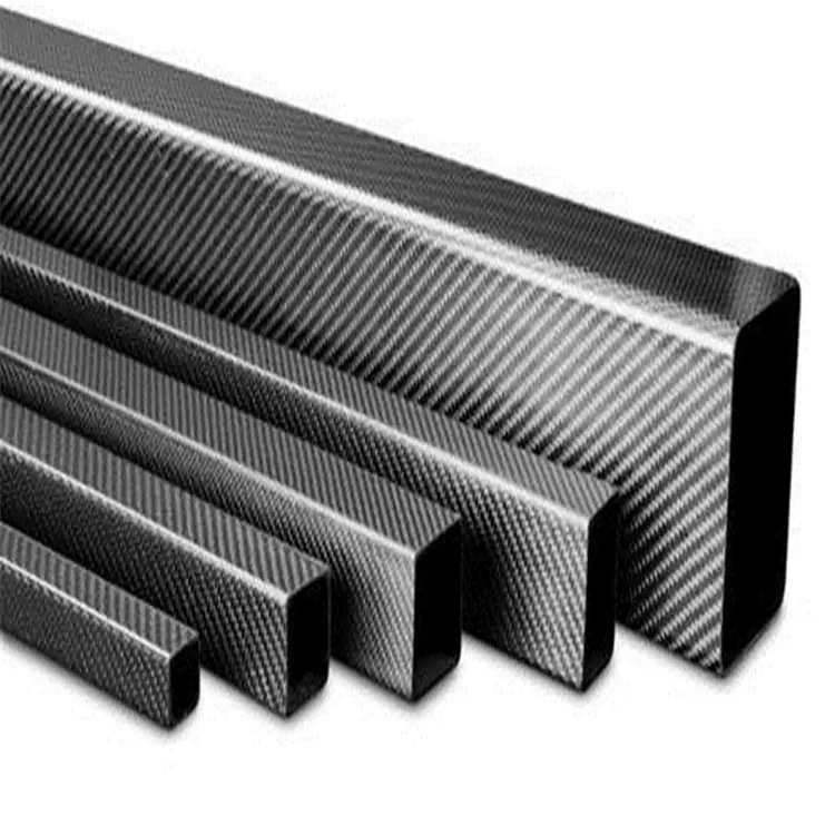
Rectangular carbon fiber tubes for machine frames(also called rectangular carbon tubes, carbon fiber rectangular profiles, rectangular CF tubes, carbon fiber box sections, or carbon rectangular tubing) are often chosen to replace metal frames because they can cut weight by 30%–50%. But once you remove mass, issues multiply: strength, stiffness, joints, impact resistance, thermal expansion, lightning protection and maintainability all demand attention. Compared with round tubes, a rectangular section adds four corners—misplaced plies concentrate stress quickly. The sections below compress lessons learned from drone frames, gantry machine tools and motion platforms into a runnable checklist you can apply directly to drawings.
1. Materials & Processes — pick the fiber first, then the method
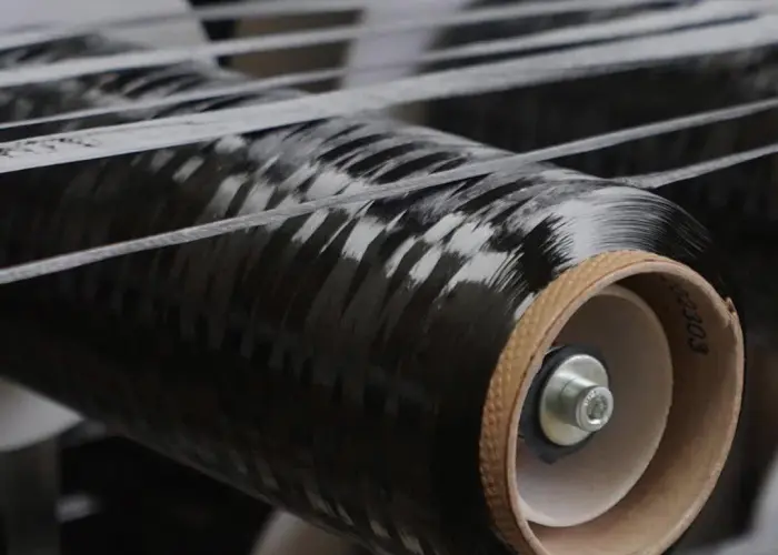
1.1 Fibers
T700S is the cost-performance watershed: tensile strength ~5.5 GPa, modulus ~230 GPa. It’s ~15% pricier than T300 and ~40% cheaper than T800. For main load-bearing beams, use T700S 12k tow; use ±45° plies for shear and 0° plies for bending. For ultra-high stiffness applications (e.g., lithography gantries) consider M40J-class high-modulus fiber — but reduce allowable strain from ~1.8% to ~1.2% and proportionally reduce design loads.
1.2 Resin
Autoclave parts: use an epoxy like the 3501-6 series, Tg ≈ 190 °C, with ~75% shear retention after hot & humid exposure. If annual volume >500 units, switch to RTM with a 6-minute cure epoxy (mold temp 140 °C, cycle ~15 min) to push porosity below 1%. Don’t substitute polyurethane in structural members — Tg ≈ 80 °C means parts will rebound in summer container heat.
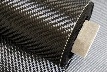
1.3 Forming
For rectangular sections prefer autoclave or hybrid pultrusion/winding processes. Pultrusion should ensure ≥60% 0° volume fraction; filament winding adds ±45° hoop layers on the outside to prevent end delamination. Inner corner radius R ≥ 2 mm — CNC chamfering otherwise severs the 0° fibers and cuts bending strength by ≥25%.
2. Strength — don’t let the “first ply” take all the blame
2.1 Ultimate load
Per ASTM D7264 four-point bending tests, a 50 × 30 × 2 mm rectangular tube (T700S/epoxy, layup [0/45/0/-45/0]₂s) reached an ultimate bending moment 1.85 kN·m, corresponding to maximum face stress ~1080 MPa. Use 0.5 × that value (≈540 MPa) as the design ultimate, and apply additional safety factors (×2) for impact and humid-heat environment.
2.2 Compression After Impact (CAI)
After 6.7 J/mm impact energy the residual compressive strength fell to ~320 MPa (~45% of the pristine part). Add a tear-resistant layer on the outside — 0.3 mm aramid or 1 mm aluminum — to recover CAI to about 60%.
2.3 Local crushing under fasteners
When sidewalls are clamped, 45° shear cracks often initiate under washers. Use 6061-T6 aluminum sleeve inserts, outer diameter 6 mm larger than the hole, length through the wall thickness; this raises crush strength from 280 MPa to 480 MPa and allows preload increase from 8 kN to 14 kN.
3. Stiffness — E is not the only variable
3.1 Equivalent bending stiffness
(EI)eq=Σ(Ei×Ii)(EI)_eq = Σ(E_i × I_i)
A 50 × 30 × 2 mm carbon rectangular tube measured (EI)eq≈1.9×10⁵N⋅m2(EI)_eq ≈ 1.9×10^5 N·m^2; the same size in 6063-T5 aluminum is only 0.42×10^5 N·m^2. Reducing wall from 2.0 → 1.5 mm keeps ((EI)_eq ≈ 1.4×10^5 N·m^2** and drops weight ~25%, but critical lateral buckling load falls from 38 kN to 22 kN. When stiffness margin exists, reduce wall before reducing section height — height influences I by the third power.
3.2 Shear stiffness
For flat rectangular tubes with aspect ratio >2, shear deformation can contribute >25% of total deflection. Reserve ~25% of your plies as ±45° to raise G₁₂ above ~18 GPa; otherwise FE results overstate “rigidity.”
3.3 Dynamic stiffness
For gantry beams spinning or excited >1,500 rpm, dynamic stiffness matters. A symmetric layup like [0/45/90/-45]_s minimizes coupling term B and avoids whirl. In tests the same beam with asymmetric layup showed 3.2 mm amplitude at 1,180 rpm, while symmetric layup only reached 1 mm at 1,600 rpm.
(Here — mid-article keyword placement)
Note: when designing frames using rectangular carbon fiber tubes / rectangular carbon tubes, check both static and dynamic stiffness early in the process.
 4. Joints — transfer load to metal
 4. Joints — transfer load to metal
4.1 Adhesive + fastener hybrid
Adhesive alone peels at ~20 N/mm; bolts alone create a hole stress concentration factor ~6. Combine them: apply an epoxy structural adhesive (e.g., DP460NS, shear ~25 MPa) then install M6 stainless bolts at 60 mm spacing. Measured joint slip <0.05 mm, fatigue: 10^6 cycles without loosening.
4.2 Insert design
Machine a 0.5 mm knurl on the aluminum insert surface and anodize; roughness Ra ~6.3 μm doubles pull-out from 4 kN → 8 kN. Add a 2 mm boss on the insert face so, when pressed in, the boss sinks into the tube interior — this avoids “hard points” that crack outer plies.
4.3 Grounding & lightning protection
Carbon tube bulk resistivity ~1.5×10⁻³ Ω·cm, ~3 orders higher than aluminum. Use 25 mm² tinned-copper braid straps, crimped with copper lugs, bolted to inserts to ensure <0.1 Ω equipotential bonding. For outdoor equipment add a 50 μm copper mesh layer; under a 50 kA lightning strike the surface ablation <0.2 mm, internal structure intact.
5. Thermal & moisture effects — don’t wait for summer to think about CTE
Longitudinal CTE (0°) ≈ −0.1×10⁻⁶ /°C, transverse ≈ 28×10⁻⁶ /°C — about 80× mismatch with aluminum. A 3 m beam with ΔT 40 °C yields ~3.4 mm differential expansion between aluminum inserts and carbon tube. Solution: fix one end and allow the other to slide with an 8 mm oblong slot + stainless steel slider; tested 2,000 thermal cycles with no shear cracks in adhesive.
At 0.3% moisture uptake Tg can drop ~15 °C and interlaminar shear fall ~12%. For outdoor parts coat with ≥120 μm polyurethane paint (WVTR < 0.8 g/(m²·day)) to reduce uptake below 0.1%.
6. Design checklist (printable — stick to your monitor)
Ultimate load ÷ 2 = design load
0° fiber volume fraction ≥ 50%
±45° plies ≈ 25–30% of total
Inner corner radius R ≥ 2 mm
Insert OD ≥ hole diameter + 6 mm
Adhesive + bolt hybrid; bolt spacing ≤ 8 × wall thickness
If thermal mismatch > 1 mm, add sliding interface
If impact energy > 6 J/mm, add tear layer
Outdoor parts paint thickness ≥ 120 μm
Grounding resistance < 0.1 Ω; copper mesh ≥ 50 μm
Conclusion
Rectangular carbon fiber tubes are not “black aluminum” — they are anisotropic laminated shells. When fiber orientation, joint detailing and environmental loads are accounted for, a well-designed rectangular CF beam is ~50% lighter and ~3× stiffer than aluminum. If you miss the calculations, the first dropped screw can turn a frame into an expensive lesson in 30 ms. The checklist above consolidates three warranty returns and one 48-hour customer downtime into practical actions: follow it and you’ll have fewer “problems & reflections” slides in your next PPT about rectangular carbon fiber tubes (rectangular carbon tubes, carbon fiber rectangular profiles).